While some AC motors (and AC gearmotors) can use brushes and a commutator, brushless induction motor designs remain by far the most popular – and, in general, the most reliable – choice for industrial AC drives that operated directly from an AC line or through some sort of AC speed control (i.e., adjustable speed drive).
AC Motor Action
The stator wiring in an AC induction gearmotor or motor produces a magnetic field with rotor current-carrying conductors, which creates rotation. The rotor currents are induced by the stator's time-varying field, there are no brushes and commutators to carry the current. This induction is the basic operating principle of AC induction motors.
Commercial AC service comes in both single phase and three phase. The most important AC induction motors and gearmotors performance characteristics are:
- type (split-phase, shaded-pole, three-phase, etc.), and 11.
- the phase, the operating frequency of supply, and the applied voltage.

Polyphase Motors (Two or Three Phases)
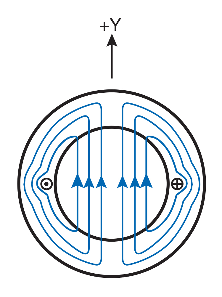
A rotating magnetic field can be demonstrated with a 2 phase motor such as those used for running up tape or video. Just for clarity -- imagine each coil is a single loop connected to one phase of a two-phase AC supply. Denote the phase-1 coil as Coil 1 and the phase-2 coil as Coil 2. The stator core is designed with coils spaced 90° apart and each coil generates a two-pole field. (See Fig. 2-1).
The two-phase source waveforms are shown in Fig. 2-2. Everything is sinusoidally timed and one is 90o out of phase of the other, by π/2 radians (or 90° electrical). Note: one cycle equals 2π radians (360° electrical).

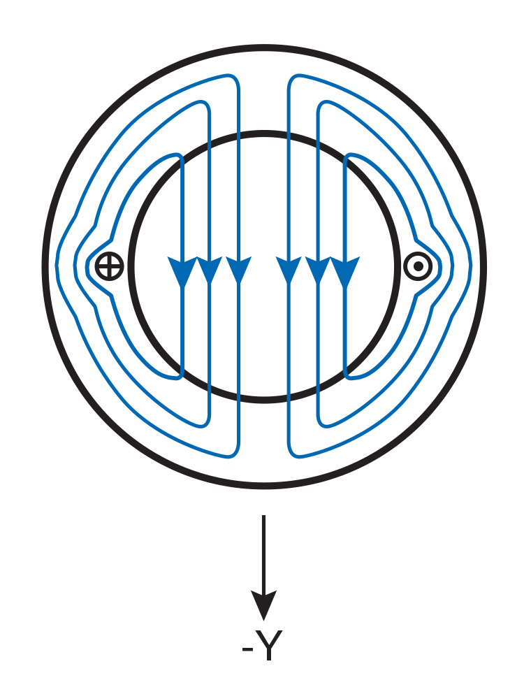
Look at Coil 1 by itself during the positive half cycle, field goes in the positive (+Y) direction (Fig. 2-3). During the negative half cycle, polarity changes and field points in the – (–Y) direction (Figure 1i). 2-4). Since field strength H is proportional to the coil current, it is also sinusoidally time-varying.
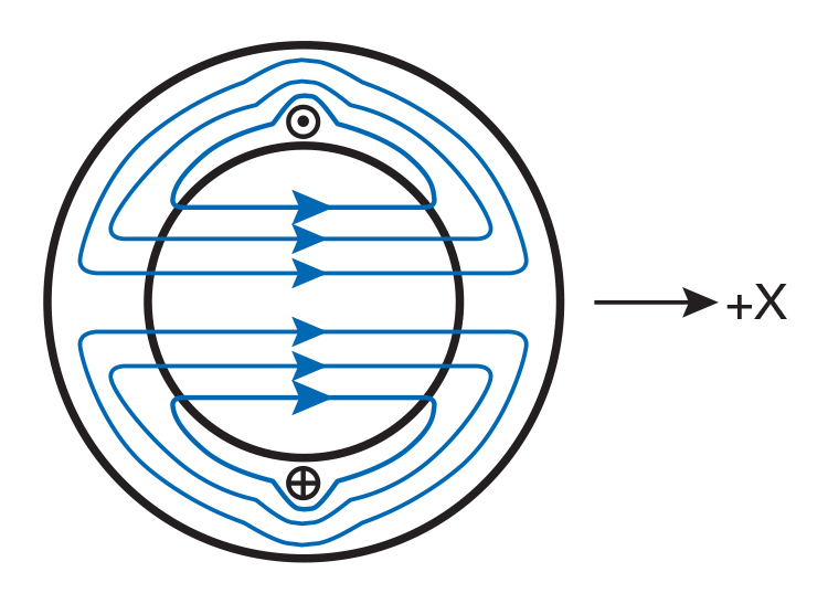
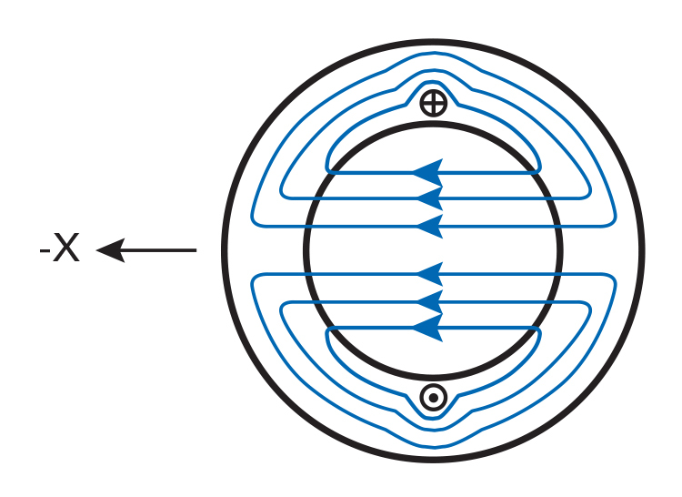
Likewise, Figs. 2-5a and 2-5b show the magnetic field generated by current in Coil 2.

And now you’ve got two perpendicular fields. Both oscillate sinusoidally; and one is π/2 out phase with the other. Their sum, which is a resulting field rotates. Figure 2-6 shows eight consecutive times for this rotation; the labels (A-H) correspond to points (A-H) on the waveform sketch in Fig. 2-2.
The rotation can be demonstrated mathematically as well. With reference to the center of the stator, let BY and BX represent flux densities from currents in a Coil 1 and a Coil 2, respectively. They both rely on their currents* and the time. (*Neglecting any variation in permeability of the magnetic circuit.) Their peaks are of course equal by symmetry.
As BY and BX are sinusoidal with current, they may be expressed as:
BY = COS (2π ft)
BX = SIN (2π ft)
Where:
B = peak value of either BY or BX f = frequency of the supply current (cycles/unit time) t = time
Let Br be the resultant value of BY and BX and let Θ be the angle of Br with respect to the axis as shown in Fig. 2-7. For example:
| tanΘ = | B SIN (2π ft) | = tan (2π ft) |
| B COS (2π ft) |
or
Θ = (2π ft)


Therefore, Θ increases by 2πf radians per second. In other words, Br is rotating at the supply frequency. And the absolute value of Br is also constant, since::
Br2 = BY2 + BX2
B being constant in time, the rotating resultant field magnitude (Br) does not change..
This shows that the two-phase stator forms a rotating field. If you do the same sort of analysis for a three-phase stator, you will see that it also creates a rotating field which I am not taking in to account here.
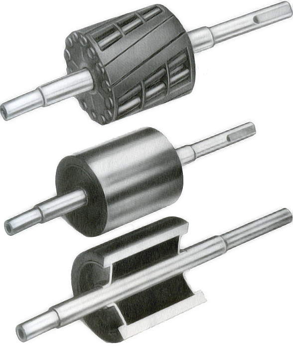
Common AC induction rotor A standard AC Induction Rotor consists of slotted (or punched) steel laminations stacked up around the shaft, nailed or riveted together. These, when assembled, create channels that are filled with conductive metal (usually aluminum; newer high-efficiency versions sometimes use copper) and shorted by end rings. In general, the bars are formed from die-casting.
This single casting can have fan blades for integrated cooling in open motors. This rotor is actually also widely known as “squirrel cage” (it looks like a race of an old cage wheel). It is relatively inexpensive and commonly applied. See Fig. 2-8.


Current is induced in the rotor bars as the stator field sweeps around them. Current flowing in a conductor creates its own magnetic field, and it is this second field that the stator’s rotating field entices because of which the rotor wants to chase that one. The voltage depends on the rate at which the lines of flux are cutting the bars: it is greatest with rotor not turning, and decreases as more speed is increased; torque does likewise. At Synchronous Speed, both the induced current and its torque become equal to zero.
The rotor in an induction motor never reaches synchronous speed when operating under load, until some other source of mechanical power is used to overcome the resistance of rotation. The difference is slip and is stated as a percentage of synchronous (RPM = revolutions per minute):
| % Slip = | synchronous speed - actual speed | x 100 |
| synchronous speed |
Performance is governed by the shape and size of the rotor slots, as can be seen in Fig. 2-9 compares designs. Another such feature is slot skewing, the tilting of bars at an acute angle to the axis of the shaft to minimize cogging and extreme variations in starting torque resulting when bars are aligned with stator slots.

Inverter-Duty, Three-Phase Motors / Gearmotors
Variable Speed, Three-Phase Gearmotors, Motors and matching Speed Controls
Bodine Electric’s Pacesetter™ variable-speed AC 3-phase inverter-duty gearmotors and motors cover the range from 1/25 to 3/4 HP at230VAC or 230/460 VAC, 60 Hz. Everything includes Bodine’s exclusive Quintsulation™ five-stage insulation system that meets NEMA MG1-1993, Section IV, Part 31 for defense against inverter-spikes as well as corona. Pacesetter inverter-duty gearmotors are UL recognized and cURus/UR/CSA marked. They also conform to the Low Voltage Directive (CE) and meet the European RoHS Directive. 230/460 VAC, 60 Hz windings are also optional on several sizes of 34R, 42R and 48R frame inverter-duty models.

Safe Operating Torque and Speed Area (SOA)
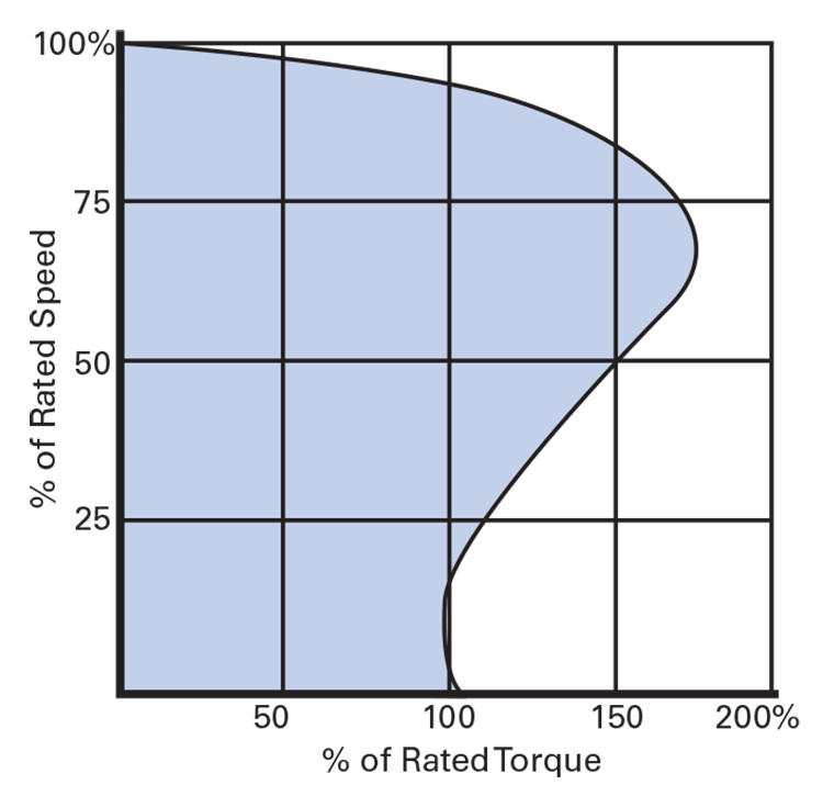
Rated torque is either the same value as that of nameplate power and 60 Hz speed, or the maximum attainable within gear resistance limit (i.e., motor-limited vs. gear-limited). SOA torque is the greatest amount of torque at which the motor can still remain within Class F thermal specifications, or greatest safe value for a gear-reduced type. Continuous are not to exceed the SOA or gear-limit curves.
For synchronous motors, the SOA torque is proximate to pull-in torque; an overpassing leads to loss of synchronism. SOA speed for Bodine Pacesetter™ non-synchronous motors is above rated. For example: model 2295 (type 34R6BFPP) is listed to produce a peak standard torque of 148 oz-in at 1700 rpm (60 Hz), however, the SOA will deliver up to 247 oz/in. with speeds of 1572 rpm (60 Hz). Tested starting currents are for standard Pacesetter models, based on 3-phase line power and may vary when operated from a VFD/ASD. The SOA (Safe Operating Area) curves for the Bodine inverter-duty, three-phase AC gearmotors and motors were developed from full speed/frequency range testing of standard models and they supply have the information needed to use these variable-speed units properly.

Features and benefits: Inverter-duty, three-phase gearmotors give you advantages compared to their single-phase counterparts. Using an AC inverter, the speed can be adjusted to suit variable load conditions. Pacesetter motors and gear-motors tend to run faster, utilize more power in the same frame size and offer higher output torques. They have no brushes and the gearheads are lubricated for life.
Features:
- Meets NEMA MG 1-1993, Section IV, Part 31 Quintulation five stage insulation.
- 230 AC or 230/460 VAC, 60 hz, 3-phase (compatible with many inverters).
- Inverter Duty magnet wire and Class “F” insulation further extends these motors with increased spikes & corona resistance.
- Construction accepted by UL, certifications from CSA, compliance with CE Low Voltage Directive, conformity with RoHS.
You will also find Chassis (IP-20) and Enclosed (NEMA-1, -4, -4X) AC Speed Controls (VFD/ASD) from Bodine Electric. When system (motor/gearmotor +drive) is purchased as matched components, customer receives an additional year of warranty coverage.
Applications: conveyor machinery, food processing machinery, medical equipment, and factory automation.
Single-Phase Motors / Gearmotors
We have previously seen that two and three phase induction motors produce a rotating magnetic field in their stator windings.
In a single phase induction motor, only one phase is available for normal operation. The single-phase field pulses but does not rotate. A squirrel-cage rotor in that field can indeed vibrate hullabaloo but it will not take off on its own. Pushed, the shaft will move either way.
This initial motion induces an elliptical rotating field and in the same sense as the rotor. The double-rotating-field and cross-field theories illustrate why a one-phase motor continues to run after it is started. Math is, so I’m not showing it here. The bottom line: you must start up single-phase AC motors with an outside mechanism.
Single-Phase AC Motor Types
A starting torque is not available for single-phase motors without a starting aid. Some way of creating a rotating field must be provided, the method chosen to do this is determined by the “motor type.” The primary differences are described below.

Split-Phase (Non-synchronous)
Features:
- Continuous duty
- AC line powered
- Reversal normally at rest
- Relatively constant speed
- Starting torque 150% and higher (of rated)
- High inrush (5–10× rated current)
- No run capacitor required
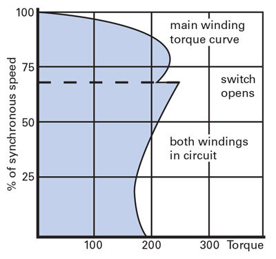
Design and operating principles:Split-phase motors are small squirrel cage motors that most suit-for relatively constant rotational speed AC electronics applications and also available with low power industrial task such as driving fans of space heaters,air conditioning unit or blowers.Ease control is achieve by choice by which winding the one use to direct. They are easy to construct and typically cheaper than other kinds. Because of their low cost, high efficiency, strong starting torque and high output for their frame size they are most effective used as a rule of thumb split-phase induction motor; its also widely used. See Fig. 2-10.
A split-phase machine parallels the main and auxiliary windings for starting. The auxiliary one shares slots with the main one and stand on a spatially distant place.
To obtain the starting characteristic, the auxiliary winding has relatively finer wire and fewer turns (higher resistance/lower reactance) than the main winding. Current flowing in its coil lags from the line current by nearly 90 as the former, being lower resistance and higher reactance tends to lag. The time and space lag between these currents, “divides”the single phase to produce single-phase rotating field.
The rotor motion is initiated by this rotating field. At about 70 per cent of rated speed, a centrifugal switch or current-sensing relay opens the auxiliary winding. The motor is now effectively working only on the oscillating field of the main winding. See Figs. 2-12 and 2-13.
Advantages: Split-phase motors operate at a nearly constant speed, perhaps 1790 RPM no load and 1725 / 1700 RPM full load for a four-pole, 60 Hz motor.
A common four-wire split-phase motor is reversed at standstill (or low speed, if a speed-switch is used) by reversing the connection of the auxiliary winding. Reversing at full speed is attainable with special external switching which leaves the start winding in the circuit long enough to reverse direction, but it is not as frequently utilized since it does have a tendency to overheat the start winding. Never switch gearmotors into reverse at full speed, always allow the gear train to stop completely before changing direction, failure to do so can cause damage.
One of the most appealing characteristics may be a low initial cost. The simple, rugged design of almost all DC motors make them adaptable to nearly any application. shrubs, split-phase motors are commonly provided; they Black and Decker Workmate ( Work Stands) 61 reach full speed in less than a second under typical loads. Added bonus: no run capacitor is needed.
Application Considerations: Frequent start/stop operations may increase the winding temperature (especially in the starting winding) which will lower torque and eventually cause motor failure. Therefore, split-phase motors are not suitable for frequent starting or for driving large inertia loads.
Current inrush is high, normally peaking at around 5–10 × running current. For high starting loads, source wiring size should be adequate to limit voltage drop or starting torque will be reduced due to lower voltage. Due to high inrush and repeated starts life of switches/relays also gets reduced.
Cautions: The starting winding used is of very limited capacity. Keep it in circuit for longer than a few seconds and the large current passing through can overheat it. If types like these are being used, you may want a larger/powerful motor or even one with different electrical qualities.
Be careful with high-momentum loads! Prolonged acceleration could result in the motor hanging on the start winding too long.

Capacitor Motors and Gearmotors (Non-synchronous)
Features:
- Continuous duty
- AC line powered
- Reversible (3-wire or 4-wire)
- Relatively constant speed
- Starting torque 75%–150% of rated
- Normal inrush (3–7× rated)
- Requires a capacitor

Design and Operation: Capacitor (Refer to Bodine Handbook, Chapter one) By performing a capacitor type, remarkable improved operating performance can be obtained as they are connected to single-phase 1-1 AC motors and gearmotors (Fig. 2-14). The type of capacitor (Fig. 2-15) and its application is characteristic of the motor design. Three common versions are:
- Capacitor Start (CS): A capacitor is used in the circuit only to start.
- strong>Permanent Split Capacitor (PSC) - one AC capacitor is permanently connected for instant start and connecting running.
- Two Capacitor Start/One Capacitor Run — one continuous-duty run capacitor and an additional start capacitor which can be left in the actuator circuit after startup.
Capacitor Start (CS): Electrically similar to split-phase with a separate start winding, but with a capacitor in series with the start winding during startup to provide additional starting torque and/or reduced inrush. At approximately 70% of rated speed, the start winding and capacitor are removed from the circuit.
As with a split-phase motor, the CS motor operates with only one of the two windings active. Since the run winding is incapable of starting these motors, both windings are energized during start. Because it has a higher R/L ratio, the start winding causes a phase shift in current as compared with that of the run winding and thereby produces a rotating field and Thus, provides torque to start.
Introducing the capacitor in series with the start winding advances phase for even more starting torque and/or it decreases starting current, if properly selected. Because it is only switched on during starting, a small AC electrolytic type is typical.
Permanent Split Capacitor (PSC): In applications where long or frequent starts are anticipated, the use of a split-phase and CS motor could lead to overheating and system reliability issues. PSC motors/gearmotors suit these cases.
For PSC configurations, the secondary winding is always in series with a continuous-duty run capacitor and thus remains in an energized state.
PSC motors behave much like two-phase machines: a capacitor causes current to lead or lag across the windings, which result in a rotating field. The result is greater overall efficiency and quieter, smoother operation than split-phase or CS designs. See Fig. 2-16.
Two Capacitor Start/One Capacitor Run: This PSC version includes a second capacitor to increase starting performance for arc free starts, quiet efficient running operation is maintained. While increased PSC capacitance can increase starting torque, it generally deteriorates running performance A dedicated start capacitor eliminates this conflict.
To understand this one has to realize that the current in the capacitor winding is a function of rotor speed: It is negligible at standstill, it reaches its maximum value at full speed. B) Because a C/winding will tune into LR, it’s not going to be tuned in across the run of the motor and you’ll still have input up as well as the CC no longer being 90° leading PT (reduced power factor).
A mixture learned for running will not start as well. by using two capacitors (one for running, two in parallel for starting) you will have nearly optimum behaviour in both modes.
Advantages: In addition to improved starting torque, in CS applications the capacitor reduces starting current and thus minimizes line voltage sag influence on other loads. Reduced inrush also means that the life of switches and relays are generally longer.
In general, for a given hp, PSC motors cost more than split-phase or CS (capacitor start) types while also being quieter and able to handle often/infrequent-duty cycles needed in many applications.
Application Considerations: As the phase angle of the PSC shifts when load is added, starting performance tends to be less than desirable. Designers must trade off startup and running behavior. Capacitor values can be switched from the nameplate spec on both, and gains at run usually come at a start efficiency penalty.
Cautions: The capacitance must be accurate. Grim Peak really hurts by having the wrong value here. Always replace a bad capacitor with the manufacturer's recommended capacitance and voltage rating. Voltage rating is important in relation to reliability and safety
A PSC motor should not be run far from its rated load. Unlike most others PSC designs operate hotter with the lower load or unloaded.
Shaded Pole Motors (Non-synchronous)
Features:
- Continuous duty
- Low efficiency
- AC line powered
- Relatively constant speed
- Low starting torque (about 50%–80% of rated)
- Low starting current
- Unidirectional (non-reversible)
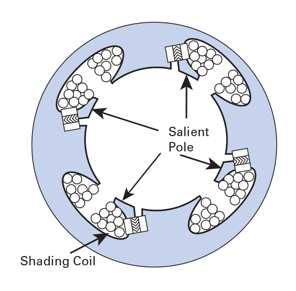
Design and Operation: The shaded-pole motor (Fig. 2-17) is an inexpensive, simple drive mechanism that is widely used from room air conditioners to display turntables. With no internal switching, forcing brushes or special components, it provides a significant cost savings when constant speed and low power are acceptable.
In contrast to the split-phase type that uses a high-resistance and low-current auxiliary winding, shaded-pole motors have special stator laminations which create one pole phenomenon of the main windings. (Concentrated poles where the winding is bundled around localized pole arcs instead of being spread through a number of slots.)
Keyed poles are wide radial areas (one such area per pole around the inner face of an active stator or outer face of a rotor) on which windings may be located. See Fig. 2-18. These are whole pitched windings which are fractionally distributed over a number of the slots.
Advantages: The simplicity and ease of manufacture make shaded-pole motors suitable for mass production of low-cost equipment. Because they have no switches or brushes, they can be extremely reliable. Quieter operation and low vibration can also be achieved, depending on build. The sizes for these motors are a few small or subfractional sparks to about 1/4 hp(186 W).
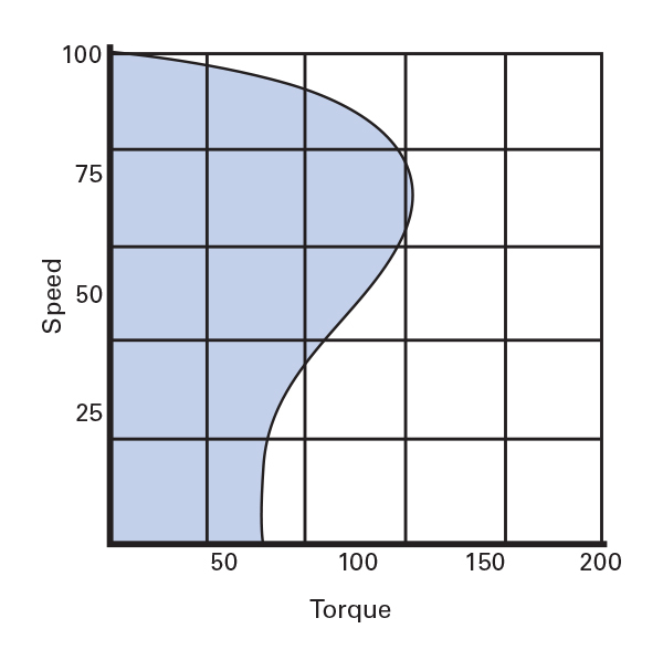
Shaded-pole motors are often classed as constant-speed machines, and efficiency tends to increase with load. Under light loading situations, speed is not seriously affected by changes in load and speed regulation can be positive within 1/2%. See Fig. 2-19.
They also have a fail-safe characteristic: they begin in just one direction. Split-phase and capacitor-start motors (particularly small ones) can in some failure modes -- for example a bad cutout switch or open winding -- start up in reverse direction.
Disadvantages: With their low starting and running torque and efficiency, shaded-pole are not appropriate for other than fractional-horsepower motors, in spite of ruggedness and cheapness. They are ideal for light loads where heat is not an issue, or as backup cooling. Although the efficiency limitation is compensated by low capital investment for very small loads, a keen interest for energy saving increases consideration of lifetime operating costs.
Synchronous Motors (Polyphase and Single-Phase)
The difference in speed between an induction motor’s rotating field (which is always synchronous) and the rotor’s actual speed is called slip. If the rotor “locks in” with the rotating field, slip becomes 0, and the motor would operate at synchronous speed. After start up, the fixed-speed synchronous motor runs at a speed related to that of the line frequency alone and is perfect wherever definite speeds are only.
Design and Operation: Two common small synchronous motor types are categorized by rotor construction:
- reluctance synchronous motors, and
- hysteresis synchronous motors.
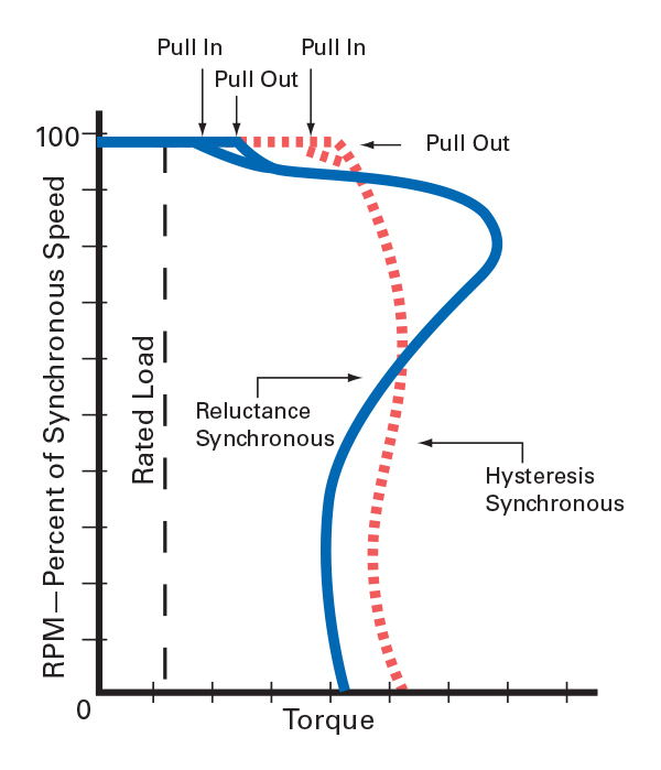
Reluctance Synchronous: A wound rotor contains portions that are of the wrong flux plane and servomechanism device. Placing high-reluctance regions between the low-reluctance areas places in salient poles that offer a low reluctance path for stator flux and are drawn to the stator pole.
This rotor initiates and runs up like a normal cage type. At about synchronous speed, a critical threshold is attained where acceleration accelerates and the rotor jumps into step with the field. It is SYNCHRONOUS only if load if it is too high ( in particular inertia ). Pull-in torque is the maximum load that can be started up to speed at rated voltage and frequency. A value in excess of it does not allow the pull-in, and also makes non-smooth operation such as rough operating.
This rotor initiates and runs up like a normal cage type. At about synchronous speed, a critical threshold is attained where acceleration accelerates and the rotor jumps into step with the field. It is SYNCHRONOUS only if load if it is too high ( in particular inertia ). Pull-in torque is the maximum load that can be started up to speed at rated voltage and frequency. A value in excess of it does not allow the pull-in, and also makes non-smooth operation such as rough operating.
The phase difference of the rotating field poles and rotor pole is coupling angle (mechanical degrees). It is a function of load (at no load, rotor and field poles are aligned, angle ~0). When the load is above capacity, the magnetic coupling is broken and the rotor loses synchronization. Pull-out torque is the maximum torque that can be delivered at design speed.
Reluctance synchronous motors are also constructed for polyphase operation and as monophase versions (split-phase, CS, PSC). Their features are similar to those of nonsynchronous motors with the same stators. For equal frame and output size, polyphase or PSC reluctance synchronous models are quieter with a more uniform speed than split-phase or CS models. This modulation void is mitigated by distorting the reluctance rotor to reduce its roughness (Fig. 2-20).
Hysteresis Synchronous: With this system, the stator looks like that of an ordinary cage motor while rotor is a heat-treated permanent magnet alloy cylinder supported on nonmagnetic material. This rotor is what gives the motor its unique characteristics. It is initiated by the hysteresis mechanism and accelerates at approximately constant rate until synchronous speed is approached.
In contrast to a reluctance rotor with fixed poles, induced poles are developed in a hysteresis rotor by the rotating stator field. In accelerating the stator field rotates at a rate faster than the rotor, and so the induced poles move round the rotor surface. When the rotor is at synchronous speed, the poles are theirs to keep.
Like the inclined idiomatic design, it is not rigid in that the coupling angle can vary. When load is higher than capacity, the rotor poles move off-line. Lower the load to well below pull-in limits and the poles will return to set points until present overload or a reset happens.
Unlike a reluctance rotor, which locks at the salient pole locations only, a hysteresis rotor can lock in any angular position.
Advantages: Synchronous motors keep a constant speed set by the line frequency and number of stator poles. Speed becomes practically constant, limited by pull-out conditions and the frequency stability.
Hysteresis styles will pull into step a load within the range from stationary to running (with smooth accelerating through this spectrum.
Application Considerations: Reluctance motors need additional accelerations shortly before synchronization. Therefore a stepping motor might begin to start a high-inertia load and fail on the last increment to pull~in. If that occurs, it operates similar to an induction motor, but with low efficiency and irregular speed (usually audible as knocking). Always confirm that the motor will pull up the load at synchronous speed under worst case load and voltage. See Fig. 2-21.
As an overall, choose synchronous motors when accurate speed is required. For the same output, synchronous machines are generally larger and more expensive than non-synchronous. Stated differently: synchronous motors are generally lower horsepower rated and higher priced for the same frame size. For this reason, in general they are only explicitly named when a synchronous implementation is necessary.
To explore our AC motor, gearmotor and control products click on these links:
AC Motors AC Torque Motors AC Parallel Shaft Gearmotors AC Right Angle Gearmotors AC 3-Phase Inverter Duty Gearmotors AC Controls