AC Inverters (VFDs) for Variable Speed Applications
Posted by Sarah Prais on Sep 23rd 2025
Standard AC motors provide low-cost, dependable power for driving other equipment. But there are tradeoffs. They run at one fixed speed, and to get anything slower you need sprockets or a gearbox.
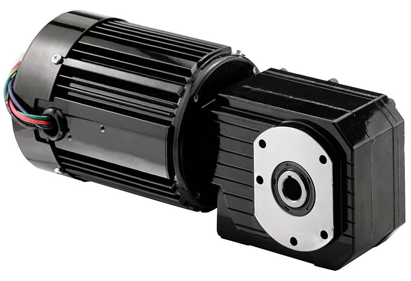
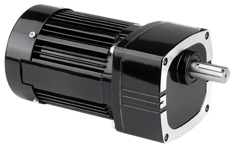
230 VAC or 230/460 VAC usable three phase winding AC inverter-duty (variable-speed) gearmotors with insulation system designed for inverter service. This enhanced insulation system provides over current protection for high voltage transients caused by PWM technology IGBT linkage.

By rectifying 60 Hz AC incoming power to DC first, inverter drives (also known as variable frequency drives, or VFDs) allow AC motors to be operated over a range of speeds while mitigating start-up inrush current. ìPower transistors (IGBTs) then “chop” the DC at a higher frequency to produce a sinusoidal output to the motor. Output voltage and frequency of the control are varied to change speed of the motor.
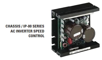
AC Speed Control (VFD) Options
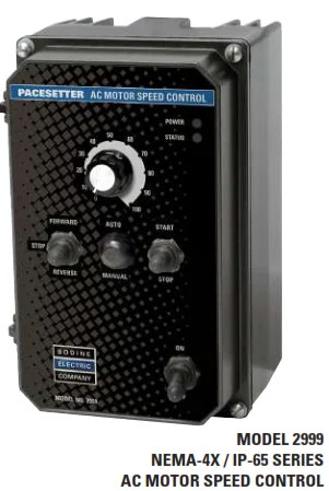
We offer three enclosure types for our AC drives. A few taps and you are controlling your AC with stock AC controls from the factory. The majority of Bodine inverter-duty users operate our gearmotors in an open-loop speed control mode, such as on conveyors, feeders or metering pumps. We are also behind OEM custom builds where we add encoders and other feedback devices to our inverter-duty gearmotors and motors.
V/Hz inverters (basic)
This is the most elementary type of drive. V/Hz drives do some pulse width modulation to generate an output waveform that is an approximation of a variable frequency sine wave, with the voltage proportional to the selected frequency. Usable speed of operation is restricted, torque regulation being rough.
Flux Vector Drive (open loop)
If a tighter degree of motion control is required an open-loop flux vector drive can be used (no encoder needed). The obvious advantages are better deviation (speed) regulation, wider speed range and the addition of digital features such as readouts, network connections and programmable parameters.
Vector Drive System (closed loop)
For ultimate accuracy or fire positioning (servo like), use closed-loop vector system. The VFD is getting shaft speed/position back from an encoder. These are the highest performance systems, but are also more complex and costly.

- Check the Line Frequency (Hz) Setting – If the motor is operated with a drive and your inverter-duty gearmotor seems to be running hot, verify that the drive’s setting matches the motor’s rated voltage and frequency. Bodine INVERTER DUTY Gearmotors operate on 230/460 V, 60 Hz. Lots of motors meant for Europe/Asia are defaulting to 50 Hz. If the Inverter is for 50Hz, it can over voltage the motor at every frequency point and rise in temperature.
- Check the Nameplate Specifications – Ensure that your VFD’s input voltage is consistent with your drive and gearmotor nameplate values/ratings. Please see the user manual for details.
- Check the Voltage and Wiring Diagram – For dual-voltage inverter-duty gearmotors or motors with 8–10 leads, follow the manufacturer's diagram to connect for 230 VAC or 460 VAC as necessary. Mis-wiring can result in insufficient performance, a no-start condition or that the motor or control is damaged.
- Check the Control Settings – There are many parameters in a VFD that impact temperature and performance. One such instance is Torque Boost. An inverter-duty duty unit may not produce the same torque at low frequency as when it's running faster. Torque boost raises the output voltage at low Hz in order to regain torque at that speed.
Check these control settings before making any connections:
- Make sure the HP, voltage, and frequency jumpers are for motor nameplate as well as supply.
- If a GFCI is used, choose the correct switching frequency jumper.
- Select Constant Torque or Variable Torque to the load profile.
- Verify the automatic restart configuration.
- Check the run / fault relay outputs and programming with regard to it.
5. Check the Rated Speed – Inverter duty gearmotors will be warm to the touch with TEFC units in the 10–90 Hz range. Our inverter-duty gearmotors are built for a long-lasting performance ratio over their operating speed/frequency range (10-90 Hz). Check the SOA graph for the device in question to ensure that it operates within acceptable limits.
To download this blog article as a PDF, please click here.
Copyright Bodine Electric Company © 05/2020. All rights reserved.