Brushless DC Gearmotor and Motors
Section 3.1 of the Bodine Electric Handbook describes the operation of a conventional permanent magnet DC (PMDC) motor. In that design, there is mechanical switching of current through the armature by a segmented commutator rotating in a fixed magnetic field. Inverter is not required because it does not have to follow the rotation, however the magnetic field itself is rotated in case of BLDC. Here the commutation occurs through electronic means as the direction of current supplied in the stator at any given instant is varied periodically according to the magnetic field position of the rotor. Brushless DC motors, also known as electronically commutated (EC) motors, need a source of controlled electricity.
Brushless DC motors exhibit much of the properties of AC and DC motors. They utilize, like the AC-motors, a rotating magnetic field to produce rotation of the rotor. They provide a linear speed-torque profile similar to that of DC motors. Cross-sections of AC induction, PMDC, and brushless DC motors are compared in Figure 3-12. This includes an ac induction motors with stator winding as well as a squirrel cage rotor. ` The PMDC motors are provided with rotor windings, whereas permanent magnets in the stator. Brushless DC motors integrate the two: The rotor contains permanent magnets, and the stator has windings.
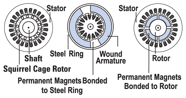
Fig. 3-12: Cross-sections of an AC induction motor (left), PMDC motor (center), and brushless DC motor (right).
Features & Benefits:
- Designed for continuous-duty operation
- Can be directly reversed at standstill or while rotating (with current limiting)
- Full rated torque across the entire speed range
- Starting torque: 175% or more of rated torque (gear limitations need to be considered)
- Noiseless, very reliable with no brushes to replace
- May need an appropriate electronic speed control
- Tach pulse output for inexpensive speed control; encoders available too.
- More thermally efficient than PMDC and outperforms traditional AC designs
- All standard Bodine BLDC have 60 degree commutation (120 degree available by special order)
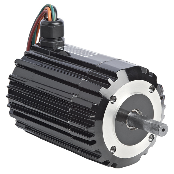
Fig. 3-13: Waveforms produced by two-phase AC.
Design and Operation: As shown in Fig. 3-13 is a motor comprising the motor portion as well as an independent electronic commutator driving unit. They need to be connected by cable or harnass first before the motor is operational (see Fig. 3-14).
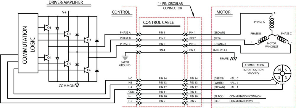
Fig. 3-14: Schematic diagram of a brushless DC motor and control.
By energising stator winding in a certain order according to the position of rotor, rotating magnet field is generated (Fig. 3-15). Sensors within the motor determine where in its rotation the rotor’s magnets are. One as the rotor moves a certain angle one senses transitioned from north to south pole magnet.
At the same time, current is exchanged to next step. By sequentially passing current through the stator windings, the rotor magnets are constantly being induced to align with the field. The current is driven just in front of the rotor, and thus speed is hard coupled to switch frequency. At each precise moment, two of the windings are energized while the third is not, so that torque from 2 phases are effectively added together to boost the overall output.
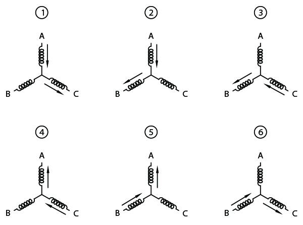
Fig. 3-15: Phase current flow
The rotor is constructed with a 4-pole permanent magnet and a reduced-scale, 4-pole sensor magnet. As the sensor magnet rotates, it actuates 60° apart Hall sensors. These sensors can be Hall-effect, photo or external encoder with commutation track. Any of these approaches supply contact position data to the controller or servo amplifier.
A binary state generator is included in the control logic that receives sensor signals and direction input relative to permanent magnets of the rotor. The logic delivers a code that is responsible for controlling the commutation of the drive transistors (Q1˗Q6 in Fig. 3-14) about which windings to be energized.
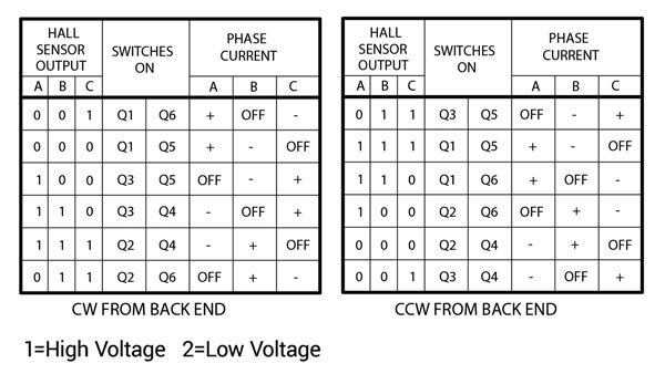
Fig. 3-16: Commutation sequence: a) clockwise left, and b) counter-clockwise (right).
Reversing of the motor direction is done with electronic reversal inside the control logic, by inverting the coil energization order. Normally you have to provide an input or external switch logic or signal that changes the rotation from clockwise to counterclockwise. The commutation truth tables are given for both the directions in Figure 3-16.
Trapezoidal vs. Sinusoidal Torque Properties: Commutation signals from the motor’s sensors determine the timing of phase “on” and “off” states.
Less commutation is required for trapezoidal a torque characteristic phase pair than the sinusoidal type. This simplifies and reduces the cost of the controls while maintaining a low ripple torque.
The commutation circuits are optimised to rectify at the point where torque and back emf in the phases are at their highest and therefore most stable. This minimizes torque ripple and variation of the phase current, which in turn results in a smoother torque output. The fixed performance also simplifies the use of digital and pulse width modulation control methods.
Advantages: Brushless motors offer increased reliability and a cleaner, quieter motor than ac or PMDC designs. There are no brushes or commutators to maintain and the motors are almost maintenance free. Solid-state circuits respond to the commutation, and they are especially beneficial where downtime can not be tolerated. Brush arcing and its resulting RFI are also obliterated.
They also have less harmonic impact than variable-speed 3-phase induction motors. The spark or electrical noise present in brush-type DC is completely obviated.
Brushless DC motors and gearmotors can provide predictable performance as a result of linear speed-torque characteristics (see curve Fig. 3-17). They offer high starting torque, click moves to exact positioning and controlled acceleration and deceleration. With the windings located on the stator frame, more power can be generated in a smaller package.
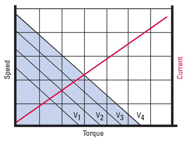
Fig. 3-17: Typical speed / torque curve for a brushless DC motor.
Brushless motors can be designed with low rotor inertia. This means they accelerate more quickly in less time and offer less power dissipation during the stop / start cycle. They are also capable of operating at high speeds since there are no mechanical commutator limitations.
They can also be designed to minimize rotor inertia which in turn reduces heat generation and improves acceleration rate and deceleration rate during start/stop operation. Without a mechanical commutator, such motors can run at much higher speeds.
Design Considerations: While Brush-DC and brushless permanent magnet DC motor drives can be reversed by reversing voltage polarity, this is not an option with electronically commutated units. Alternatively, the present feed sequence to the stator coils must be changed with a motor controller. Because of their low friction, brushless motors can coast to a stop when power is removed from them; dampening circuits may be used to address this.
More expensive: The electronics needed to operate a BLDC motor is more complicated (based on microcontroller design) than its PMDC counterpart, making it costlier. However, continuous improvements in electronics and the existence of higher quality magnetic materials have made brushless DC motors (BLDC) and BLDC gearmotors a viable alternative. Today they are viable alternatives to brush-type PMDC and variable speed AC motors.
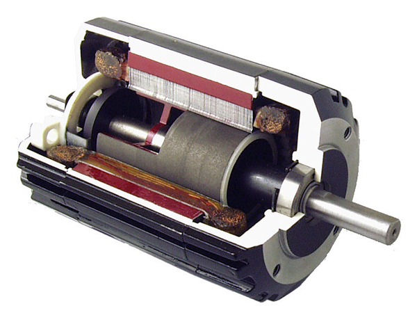
Fig. 3-13a: Cutaway view of Bodine type 34B, brushless DC motor with built-in commutator, and permanent magnet rotor.
To explore our BLDC motor, gearmotor and control products click on these links:
 Download this Handbook section as a PDF